Detecting a Siedle Doorbell with an ESP32 and Optocoupler
Intro⌗
I wanted to detect my Siedle doorbell press using an ESP32 so I could expose it to Home Assistant. At first glance this sounds trivial—until you actually put a multimeter on the Siedle line.
Siedle’s 1+n system is partially documented here: Systemhandbuch 1+n-Technik (2019)
On my installation, the doorbell line sits at ~18 V DC when idle and rises to ~22 V DC when the button is pressed. There is no clean contact closure, and the line is clearly current-limited. You are not supposed to power anything from it—only to sense a state change.
There also appear to be at least two generations of Siedle systems:
- Newer systems typically use a 12 V AC transformer (I have a TR603-0)
- Older systems often expose both 20 V AC and a 24 V DC signalling line, which rises to ~24 V DC when ringing
For reference, my indoor station is an HTS-811.
Detecting ringing⌗
After a quick Google search, I came across an excellent ioBroker forum post by Eisbaeeer describing a beautifully simple circuit that does exactly what I needed:
Siedle Klingel & Türöffner mit ESP8266 und MQTT (ioBroker Forum)
There’s also a great write-up here where someone went a step further and designed a custom PCB to implement most Siedle functions—not just ringing detection: Smart Doorbell
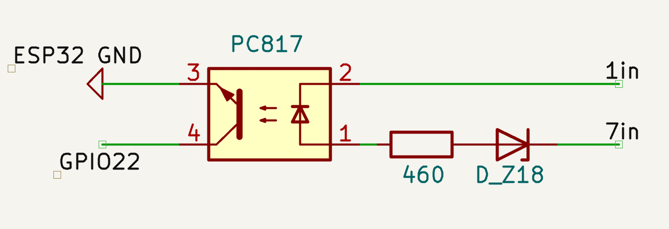
The ringing detection is done by applying the signal voltage (on pin 7) across a zener diode, which only starts conducting once its breakdown voltage is exceeded. That current then drives an optocoupler, providing full electrical isolation while pulling an ESP32 GPIO to ground.
The Circuit⌗
The detection circuit consists of only three components:
- A zener diode
- A series resistor
- A PC817 optocoupler
How it works⌗
Idle (~18 V DC) The zener diode conducts and clamps the voltage → no current through the optocoupler LED → output stays off
Doorbell pressed (~22–24 V DC) The voltage exceeds the zener breakdown → current flows through the LED → optocoupler pulls the ESP32 input to ground
This turns a small voltage step on a current-limited line into a clean digital signal.
Choosing the Zener⌗
Newer systems (~18 V idle / ~22 V pressed) → 18 V zener works well
Older systems (~24 V signalling) → 20 V zener (ZF20) as used in the original design
If the zener voltage is too high, the “low” level may sit around ~2 V, which is too high for reliable detection—even with the ESP32’s internal pull-up.
The code⌗
Here’s a minimal Arduino sketch showing how to read the optocoupler output.
// Pin connected to PC817 collector
const int doorbellPin = 22;

// Last state for debounce
bool lastState = HIGH;
unsigned long lastDebounceTime = 0;
const unsigned long debounceDelay = 50; // ms

void setup() {
  // Configure pin as input with internal pull-up
  pinMode(doorbellPin, INPUT_PULLUP);
}

void loop() {
  int reading = digitalRead(doorbellPin);

  // Debounce logic
  if (reading != lastState) {
    lastDebounceTime = millis();
  }

  if ((millis() - lastDebounceTime) > debounceDelay) {
    if (reading == LOW) { // Active-low means doorbell pressed
      Serial.println("Doorbell pressed!");
      // Do some stuff
    }
  }

  lastState = reading;
  delay(10); // small loop delay
}
Hardcoding is fine, but I prefer ESPHome for easier maintenance and Home Assistant integration. This is a minimal example configuration:
esphome:
  name: esp32-doorbell
  platform: ESP32
  board: esp32dev

globals:
  - id: doorbell_state
    type: bool
    restore_value: no
    initial_value: 'false'

binary_sensor:
  - platform: gpio
    pin:
      number: 22
      mode: INPUT_PULLUP
      inverted: true
    name: "Doorbell"
    filters:
      - delayed_off: 50ms
    on_state:
      then:
        - lambda: |-
            id(doorbell_state) = x;
The optocoupler output connects directly to the GPIO. The ESP32’s internal ~50 kΩ pull-up is sufficient—no external resistor needed.
Powering the ESP32⌗
In my case, the existing CAT3 cable carries all Siedle signals and still leaves two twisted pairs unused. Since I don’t have 24 V DC available, I added a small DIN-rail supply (a Mean Well HDR-15-5) and sent 5 V DC over a spare pair.
I terminate this into a USB-C connector, which lets me power the ESP32 (or anything else) using a standard USB-C cable.
The PoE rabbit-hole⌗
With three spare pairs, PoE sounds tempting—especially for adding wired Ethernet. Unfortunately, proper PoE would require Mode A, which is less commonly supported. Most PoE devices only support Mode B, which would need another pair, making it pointless in this setup.
Something like 10Base-T1S might be an interesting future option for adding Ethernet over a single pair.
Using a Shelly instead⌗
If you don’t actually need an ESP32 (I run a small e-paper display, so I had one anyway), this can be done even more easily:
- A Shelly “Pill”
- Or a Shelly 1 with the Add-On
Both support internal pull-ups and work well for simple digital inputs. This also lets you run 12–48 V DC over the spare wiring. At 5 V, voltage drop can be noticeable, so it’s worth measuring at the far end—but most devices are fairly tolerant.
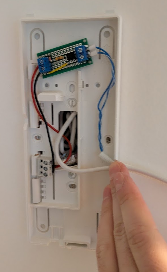
The final setup⌗
Finally a bad picture to show how easy the integration is, in my case the ESP32 is external, so I just mounted the small circuit with some VHB tape, there’s plenty of space in there!